Quick answer: the KTY83-122 is a two-wire resistive temperature sensor inside the motor. It reports temperature as a resistance signal. It does not decide anything, it does not switch anything off, and it cannot protect your motor on its own. Protection only exists when a compatible controller reads that signal, is wired correctly, and has protection parameters set. If any one of those three is missing, you have a sensor — not a protection system.
This article covers what the sensor does, what has to be true for protection to work, how to check that yours is actually armed, and the four things a temperature sensor can never do.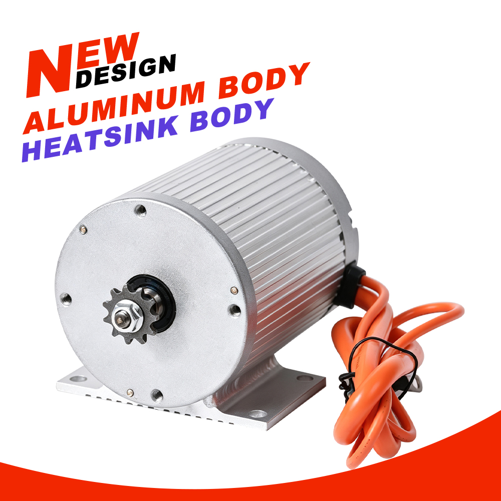
Three facts describe it completely:
In the Kunray MY1030 family, the KTY83-122 is recorded as standard across all seven voltage and power combinations (36 V / 48 V / 60 V / 72 V, 1000 W–3000 W). You do not buy it as an option.
The important consequence: because the sensor only reports, the phrase "the motor protects itself" is not accurate. Everything downstream of the signal is decided elsewhere.
This is the part most build logs skip. For temperature-based protection to actually work, you need all four of these:
The conditionality here is deliberate and worth stating plainly: the specific thresholds, the actions taken, the delays and the recovery logic are all decided by the controller, not by the motor. Two controllers reading the same sensor can behave completely differently.
When conditions 1–3 are met, the system can use the temperature signal to perform any of the following, depending on how the controller is configured:
A derate curve, a hard cut-off, and a warning-only setup are three different configurations of the same sensor. None of them is "the" behaviour — so when someone tells you a motor "has overheat protection", the only useful follow-up question is which controller, set how.
The sensor is standard on every variant, but three items are specific to your controller and your build. Get them confirmed for your combination rather than assuming a generic value applies:
Do not fill these in from a similar motor. A resistance curve is a property of the sensor and the controller's interpretation of it together. Using the wrong curve on a controller that accepts manual entry is one of the ways a "protected" build ends up unprotected — the display looks plausible while the thresholds sit at the wrong temperatures.
You can check this instead of assuming it. Work through these in order:
Two safety rules while you are doing this. Never work on wiring or connectors with the system powered. And if the sensor is not connected, or your controller is not compatible with it, you must not describe your build as having overheat protection — because it does not.
These are the four claims that show up constantly and are all wrong:
The honest framing is this: a temperature sensor converts an invisible failure mode into a measurable one. That is genuinely valuable — it lets you see the problem before it becomes a burned winding. But the value is realised by the controller's configuration and by how you build the machine.
Does every MY1030 variant have the KTY83-122? Yes. It is recorded as standard across all seven voltage and power combinations, not an optional extra.
Can I keep my existing controller and still have temperature protection? It depends on whether that controller is compatible with the KTY83-122 and whether it lets you configure thresholds. There is no single answer that covers all controllers — check the controller's own documentation, and confirm the temperature input is both readable and configurable.
What temperature will it cut off at? That is a controller setting, not a motor specification. The motor provides a signal; the controller decides the threshold, the action, the delay and the recovery logic.
What is the resistance curve of the KTY83-122? Do not substitute values from a different motor or a generic table — a curve that does not match your controller leaves the display plausible while the thresholds sit at the wrong temperatures. Request the values for your variant and controller, and get the answer in writing.
If the sensor fails or is disconnected, what happens? If the signal is not present or not read, no temperature-based protection exists. You must not assume a disconnected sensor causes a safe default — verify with your controller's documentation.
Which wire is the temperature signal? There is no colour standard across motors, so do not wire by colour alone — cross-check against the motor's nameplate and label, confirm voltages by measurement, or get the pinout for your variant from Kunray.
Is the sensor a replacement for good thermal design? No. It reports what is happening; it does not change what happens. Gearing, load, duty cycle, airflow around the finned housing and controller current all determine the heat that gets generated in the first place.


