Motor RPM must be converted through the drivetrain before it becomes vehicle speed.
This is especially important for mid-drive motors such as the Kunray MY1030, whose different configurations operate at rated speeds from approximately 3000 RPM to 4500 RPM, with higher peak speeds depending on the version.
To design the drivetrain properly, you need to connect four variables:
Motor RPM → Gear Ratio → Wheel RPM → Vehicle Speed
Once this relationship is understood, selecting sprockets becomes much more logical.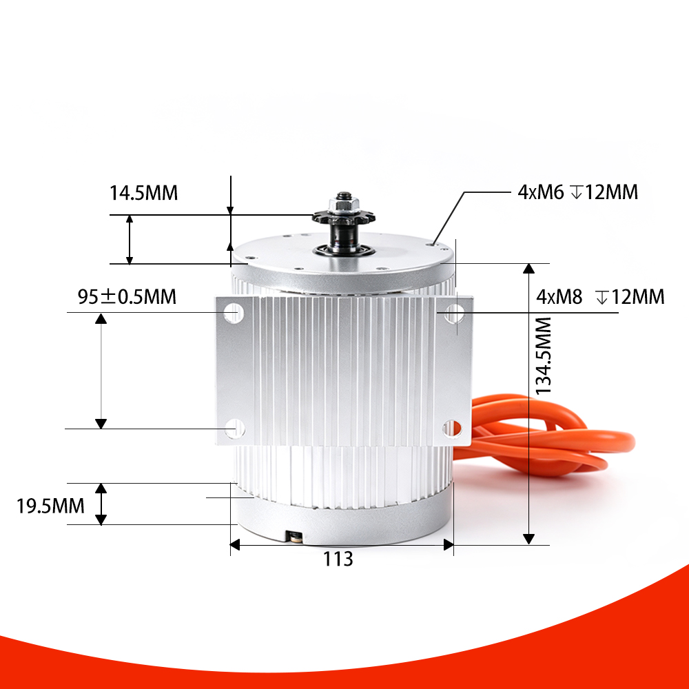
The MY1030 range includes several rated-speed configurations.
For example:
These are motor shaft speeds.
They are not vehicle speeds.
A motor turning at 4000 RPM does not mean that the wheel is also turning at 4000 RPM.
The drivetrain exists specifically to transform this rotational speed.
The simplest relationship is:
Wheel RPM = Motor RPM ÷ Total Reduction Ratio
For example:
Motor speed = 4000 RPM
Reduction ratio = 8:1
Therefore:
Wheel RPM = 4000 ÷ 8 = 500 RPM
If the total reduction ratio is 5:1:
Wheel RPM = 4000 ÷ 5 = 800 RPM
The smaller the reduction ratio, the faster the wheel turns.
Now we need the wheel circumference.
The circumference of a wheel is approximately:
C = π × D
where D is wheel diameter.
Once wheel circumference is known, theoretical vehicle speed can be estimated from wheel RPM.
For example, suppose the wheel diameter is 0.4 meters.
Wheel circumference:
3.1416 × 0.4 ≈ 1.257 m
At 500 RPM:
1.257 × 500 = 628.5 meters/minute
Converting to kilometers per hour:
628.5 × 60 ÷ 1000 ≈ 37.7 km/h
This is a theoretical value before accounting for tire deformation, drivetrain losses, voltage sag, motor operating conditions, and other real-world factors.
For quick calculations:
Vehicle Speed (km/h) ≈ Motor RPM × π × Wheel Diameter (m) × 60 ÷ (Gear Ratio × 1000)
This formula is extremely useful when designing a mid-drive electric vehicle.
It allows you to estimate the theoretical relationship between:
Suppose you are using a MY1030 configuration with a rated speed of:
4000 RPM
Your wheel diameter is:
0.4 m
You want a theoretical vehicle speed of approximately:
40 km/h
The required reduction ratio can be estimated from the formula.
Rearranging the equation:
Gear Ratio ≈ Motor RPM × π × Wheel Diameter × 60 ÷ (Vehicle Speed × 1000)
Using the values:
4000 × 3.1416 × 0.4 × 60 ÷ (40 × 1000)
The result is approximately:
7.54:1
Therefore, a total reduction ratio around 7.5:1 would theoretically place the system near 40 km/h under ideal conditions.
The actual result will be different in a real vehicle.
This is one of the most important points.
A mathematical calculation assumes the motor can maintain its specified RPM under the required load.
A real vehicle has:
At higher speeds, aerodynamic drag becomes increasingly important.
Therefore, the vehicle may not reach the theoretical speed calculated from motor RPM.
This is why gearing should not be designed solely around maximum unloaded motor RPM.
For a simple chain drive, the ratio can be estimated from the number of teeth.
For example:
Reduction Ratio = Driven Sprocket Teeth ÷ Motor Sprocket Teeth
Suppose the motor sprocket has 10 teeth and the driven sprocket has 80 teeth:
80 ÷ 10 = 8:1
If the motor sprocket changes to 20 teeth while the driven sprocket remains 80 teeth:
80 ÷ 20 = 4:1
The wheel now turns twice as fast, but the mechanical torque multiplication is reduced.
This is the fundamental effect of changing sprocket size.
The MY1030 platform provides:
These options are not simply cosmetic variations.
The sprocket is part of the drivetrain interface.
It determines compatibility with the selected chain system and contributes to the final reduction ratio.
This is particularly important for DIY builders who may already have a particular chain and rear sprocket configuration.
A common mistake is to calculate the gear ratio based only on the desired top speed.
But a vehicle also needs enough wheel torque to accelerate.
Suppose the theoretical calculation gives you a very high vehicle speed using a low reduction ratio.
The motor may be capable of reaching the corresponding RPM with little load.
But once the vehicle starts moving, the motor has to overcome:
If the gearing is too tall, acceleration can become poor.
This is why a practical drivetrain usually requires a compromise between:
Top Speed
and
Wheel Torque
One of the major advantages of a mid-drive motor is that gear ratio can be changed without replacing the motor.
This makes the drivetrain tunable.
For example:
Can favor:
Can favor:
The correct balance depends on the vehicle.
Instead of starting with the motor and asking how fast it can go, start with the vehicle.
Know the actual tire size.
Decide what speed the vehicle is expected to achieve.
Use the motor's rated speed as a starting reference.
Use the theoretical speed relationship.
Make sure the selected ratio provides enough mechanical advantage for acceleration and climbing.
The motor must be able to receive the electrical power required to operate under the intended load.
Road conditions and actual vehicle loading can significantly change performance.
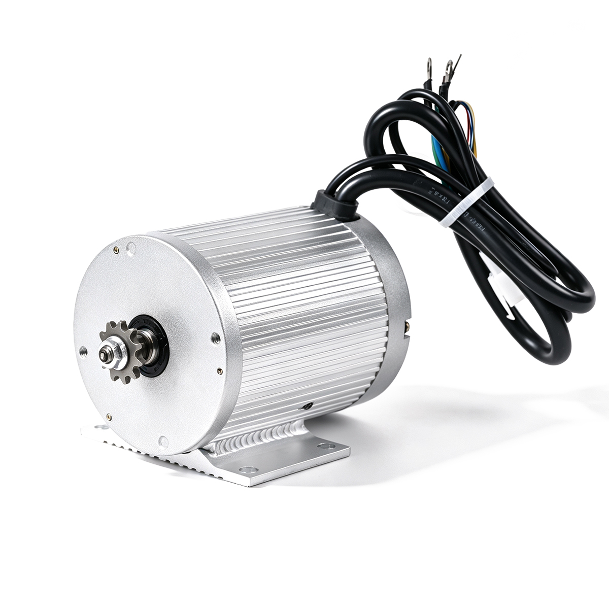
The MY1030 platform covers a wide range of rated speeds and power levels.
The 36V and 48V 1000W versions are rated at 3000 RPM.
The 48V 1600W version is rated at 3500 RPM.
The 2000W and 2500W versions are rated at 4000 RPM.
The 72V 3000W version is rated at 4500 RPM.
This variation means that the drivetrain should be designed around the specific MY1030 version rather than treating every MY1030 as having identical speed characteristics.
Motor RPM tells you how fast the motor shaft turns.
It does not directly tell you how fast the vehicle will travel.
To understand vehicle speed, you need to connect:
Motor RPM → Reduction Ratio → Wheel RPM → Wheel Diameter → Vehicle Speed
At the same time, you need to consider:
Motor Torque → Reduction Ratio → Wheel Torque → Tire Force
The best drivetrain is therefore not the one that produces the highest theoretical speed.
It is the one that provides an appropriate balance between speed, acceleration, climbing ability, efficiency, and thermal load.
For a mid-drive system such as the MY1030, understanding this relationship is one of the most important steps in designing a successful electric vehicle.


