Quick answer: in a brushless motor, the Hall sensors tell the controller where the rotor is, which is how the controller knows when to switch each phase. Their position varies by design — some motors bury them deep in the stator, some place them on an external board, and some put them inside the end cap. The Kunray MY1030 uses an end-cap-side serviceable Hall assembly: the Hall elements sit inside the end cap, and removing the end cap gives you access to them.
That is a real serviceability advantage. It is also still a teardown — opening the end cap is a disassembly operation, it should not be described as "replace them without opening the motor", and it should not be assumed that every user can do it. This article explains exactly what the design gives you, what it does not, and what to confirm with your supplier before you buy.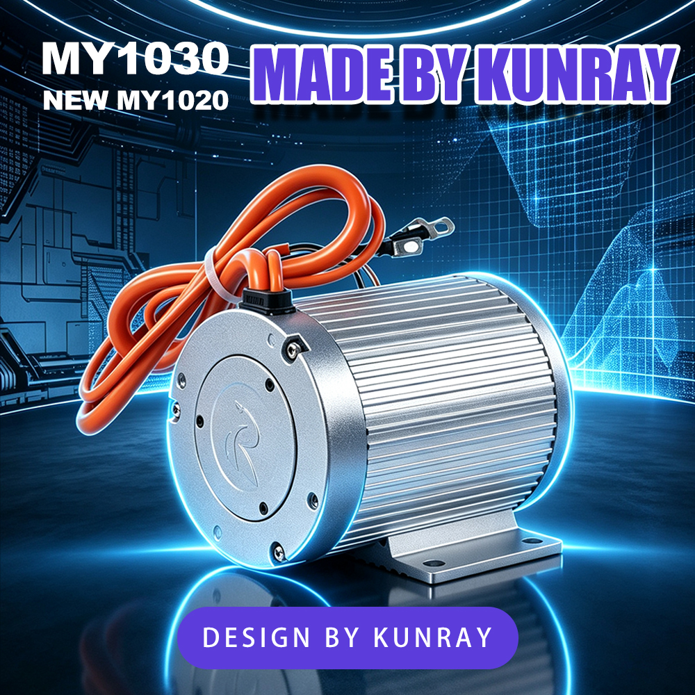
A BLDC motor cannot run on a fixed electrical pattern. The controller has to know the rotor's position continuously so it can energise the right phase at the right moment. That is what the Hall group does: it reports position, and the controller commutates on that report.
In the MY1030, the recorded configuration is:
The three signals work together with the 10-pole (5 pole pair) rotor to describe position as the rotor turns.
Because the Hall group is a position-sensing element that sits in the motor's rotating-field environment, its physical location drives three things: how hard it is to replace, how exposed it is to heat, and how much of the motor you have to disturb to reach it.
The end-cap approach is a middle path: the sensing elements stay inside the motor — where they are covered by the same IP54 protection boundary as everything else in the housing — while remaining reachable without dismantling the stator or pulling the rotor out of the windings.
Note what the design does not claim. It is not an outboard Hall board, so there is no external board, no external connector for the Halls, and nothing protruding from the housing. And it is not a "no disassembly required" design. Those are different things, and conflating them is how people end up damaging a perfectly good motor.
Three practical benefits, stated without inflation:
What it does not give you: a field-replaceable part you swap without opening the motor, a user-serviceable component, or a procedure you can improvise.
This is the part where overclaiming causes real damage. Opening the end cap means:
Because those are open items, this article deliberately does not publish a step-by-step teardown sequence. If you need to service the Hall group, request the procedure from Kunray for your specific variant rather than working from a generic tutorial for a different motor.
Two safety rules apply regardless. Disconnect power before any disassembly or connector work. And confirm rotation direction before you complete final sprocket tightening and power-up testing — the output shaft thread is M8 × 1.25 left-hand, so getting the direction wrong has real consequences for the shaft thread and the sprocket fixing.
Hall wiring is variant-specific: there is no colour standard, and the pinout and electrical angle are not interchangeable between motors. Do not re-pin the Hall wires by trial. Re-pinning by guesswork is a common "fix" that can damage a controller, and without the pinout for your variant there is no way to know whether you are correcting a fault or creating one.
Two practical steps instead:
Hall problems have a recognisable signature, though none of these is proof on its own:
What to do about it: measure before you change anything. Check battery voltage, controller status, phase connections, the Hall connector and the connector contacts. A loose or corroded Hall connector produces exactly the same symptoms as a failed Hall element, and it costs nothing to check first.
What not to do: do not assume the motor is dead without measuring, and do not work through a list of Hall wire combinations hoping one works. With the pinout still unconfirmed, that process has no way to converge and a real chance of collateral damage.
Are the Hall sensors outside the motor? No — and that framing should be avoided. The design is an end-cap-side serviceable Hall assembly. The elements are inside the end cap; removing the end cap gives you access. They are not an external, exposed board.
Can I replace a Hall sensor without opening the motor? No. Access requires removing the end cap, which is a disassembly operation. The correct description is "the Hall assembly is reachable after the end cap is removed" — not "no disassembly required".
Can I do this repair myself? It should not be assumed that any user can. It is a teardown involving the winding, the rotor magnets and the bearing alignment. If you are not confident working inside a motor, have it serviced — and get the variant-specific procedure first.
How do I know if my symptoms are Hall-related? You do not know until you measure. Check voltage, controller status, phase connections and the Hall connector contacts first. An intermittent connector is a much more common and much cheaper explanation than a failed Hall element.
Can I re-pin the Hall wires to fix a running problem? Not by guessing. Hall wiring is variant-specific, and the pinout and electrical angle are not interchangeable between motors — so there is no generic reference to work from. Request the pinout for your variant instead.
Does the serviceable design mean the motor is easier to keep running long-term? It means Hall replacement is a defined operation rather than an automatic motor replacement. Whether that converts into a real cost saving depends on the labour involved, the part cost, and whether the rest of the motor is still healthy.
Is the end cap sealed against water ingress? The motor's recorded protection rating is IP54, which covers dust ingress and splashing water. It does not permit immersion, and it does not permit high-pressure washing. Opening the end cap obviously requires the seal to be restored correctly on reassembly — which is one of the reasons the reassembly procedure matters.


